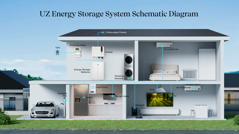
Two products can both be well designed and still fail to work properly together. A battery may be described as “48 V,” and an inverter may accept “48 V batteries,” yet that does not confirm that the pair can charge, discharge, communicate, or provide backup as intended.
Battery–inverter compatibility is not a single specification. It is an agreement across the electrical operating range, current limits, communication protocol, software versions, system configuration, and the functions that have actually been tested. If one of those layers does not match, the system may refuse to start, report the wrong state of charge, operate below its expected power, or lose functions that the buyer assumed were included.
The electrical operating window has to match
Nominal voltage is the first check, not the final answer. A low-voltage battery is often described by a familiar system voltage, but its actual terminal voltage changes as it charges and discharges. The inverter also has a permitted battery-input range. The battery’s full operating window must remain inside that range, including the limits used near full charge and low state of charge.
This is why matching two “48 V” labels is not enough. The same principle applies to high-voltage systems, where battery stacks may be built from different numbers of modules. A configuration that is electrically suitable at one stack height may fall outside the permitted range when modules are added or removed. The voltage, capacity, and current values therefore have to be checked as a system rather than as isolated numbers. For a refresher on what those specifications mean, see Voltage, Capacity, and Cycle Life: What These Battery Numbers Actually Tell You.
Current is the next boundary. The inverter has maximum charging and discharging currents, while the battery and its BMS impose their own limits. The usable system limit is set by the most restrictive component at that moment. If an inverter would need more DC current to deliver its headline AC output than the battery bank permits, the combination cannot sustain that output from the battery alone.
Those limits may also change with temperature, state of charge, cell conditions, or the number of battery modules in service. In a managed system, the battery can send updated charge-voltage, charge-current, and discharge-current limits to the inverter. Victron’s documentation shows this control relationship directly: a connected BMS supplies the current operating limits, and the inverter/charger and other controlled devices respond to them.
Adding battery modules can increase available energy and, in some designs, available current. It does not mean that any number of modules can be connected in any arrangement. Minimum and maximum module counts, parallel limits, protective devices, cable sizes, and current sharing still depend on the approved system design.
CAN or RS485 does not prove communication compatibility
The most common misunderstanding appears at the communication port. A battery and inverter may both have CAN or RS485 connections and still be unable to exchange useful data. CAN and RS485 describe communication interfaces; they do not guarantee that both devices use the same messages, data mapping, baud rate, cable pinout, or configuration.
Even an RJ45 socket does not guarantee that a standard Ethernet cable—or the same cable used for another battery—will be correct. The contacts may be assigned differently. Sol-Ark’s low-voltage battery integration guide, for example, documents different CAN and Modbus pin assignments and gives battery-specific instructions for ports, DIP switches, addresses, and inverter settings. The connector shape alone says very little about whether the two ends can communicate.
When closed-loop communication is working, the inverter can receive information such as state of charge, battery voltage, temperature, alarms, and the charge or discharge limits requested by the BMS. These values allow the inverter to adjust its operation as battery conditions change. Sol-Ark’s guide shows these fields on its CAN-bus battery screen, while Victron documents how a managed CAN-bus battery can pass dynamic voltage and current limits to connected power-conversion equipment.
Some equipment also supports open-loop operation, where charging and discharging are controlled through manually configured voltage and current settings rather than continuous BMS instructions. That is not a universal fallback. Whether it is supported, which functions remain available, and what settings are required are all manufacturer- and model-specific. A battery should not be treated as compatible simply because the inverter can be made to charge it once.
Compatibility belongs to an exact configuration
Compatibility is normally established between specific battery models, inverter models, software versions, and system layouts. It should not be extended automatically to an entire brand or product family.
Official compatibility documents make this clear. BYD’s Battery-Max Lite list identifies inverter models, permitted module quantities, firmware requirements, and parallel-connection conditions. Fronius publishes compatibility by inverter and battery model, including supported parallel quantities and qualifications related to software, country certification, and availability. These are configuration approvals, not broad statements that every product from two brands can be combined.
Firmware is part of that approval. A physically correct system may still fail to communicate if the inverter or battery is running a software version that does not support the required protocol. Solis, for example, publishes an installer procedure specifically for upgrading hybrid-inverter firmware to match a battery protocol. Compatibility should therefore be checked against the current document revision and the firmware actually installed, not against an old list or a general statement from a distributor.
The approved operating mode matters as well. A pairing may be supported for grid-connected operation but not for backup, or it may have conditions covering minimum battery quantity, parallel expansion, or a particular market. Local certification and warranty scope can also depend on the complete tested configuration. Solis advises users to select batteries from its approved list and states that unverified combinations may create communication or performance problems and affect warranty coverage.
This distinction is visible in UZ Energy’s own Sol-Ark certified battery partner announcement. The approval identifies three specific UZ Energy battery models, three specified Sol-Ark inverter platforms, closed-loop communication, and the U.S. market. That is useful compatibility evidence because its scope is defined. It should not be read as approval for every UZ battery, every Sol-Ark inverter, or every installation arrangement.
What should be confirmed before purchase?
The useful question is not simply, “Will this battery connect to this inverter?” It is, “Has this exact combination been approved for the way the system will be built and operated?”
Before equipment is ordered, the installer or system designer should confirm the exact battery and inverter model numbers, the full battery-voltage range, charge and discharge current limits, permitted module count, communication method, required cable and pinout, protocol setting, minimum firmware versions, and whether backup or parallel operation is included in the approval. The current compatibility list and both manufacturers’ installation documents should agree.
Commissioning then confirms that the approved design is working in the real installation. The inverter should display credible battery data, recognize the intended BMS, and follow the communicated limits without recurring alarms. Charging, discharging, shutdown behavior, and any required backup mode should be tested within the manufacturer’s procedure.
Battery–inverter compatibility is therefore better understood as verified system integration. Matching voltage is necessary, but it is only one layer. Reliable operation depends on the electrical limits, control language, software, wiring, configuration, and application scope all matching at the same time.