An inverter is the power-electronic stage that converts electricity between direct current (DC) and alternating current (AC). In battery storage, a power conversion system (PCS) usually refers to the wider bidirectional conversion package, which may include inverter stages, controls, protection, filtering and communications. The terms can overlap, so the required functions matter more than the label.
Confusion starts because the words describe different levels of the same electrical chain. An inverter names a conversion function or conversion stage. A PCS usually names the packaged battery interface that performs that conversion and may also coordinate grid synchronization, active and reactive power, protection, communications and operating limits.
An inverter describes the conversion stage
Solar modules and batteries operate on DC, while most buildings and public grids operate on AC. An inverter creates the required AC waveform from a DC source. In a conventional PV system, power normally moves from the solar array toward the AC system. In a battery system, the conversion equipment normally needs to work in both directions: AC-to-DC while charging and DC-to-AC while discharging.
Direction alone is not a perfect naming rule. Hybrid inverters can manage both PV and batteries, and technical documents may call a battery converter an inverter, inverter/charger or bidirectional converter. The U.S. Department of Energy likewise describes inverters as equipment that can interface either generation or storage with an AC system. A project team should therefore verify functions and interfaces instead of assuming capability from the word inverter.
A PCS is usually the wider battery power interface
In a battery energy storage system, the PCS sits between the DC battery and the AC installation. Its inverter stages perform the electrical conversion, while the wider package may include filtering, contactors or switchgear, sensing, protection, thermal management, communications and local controls. The exact boundary varies by supplier and project.
The PCS executes power commands within the limits available at that moment. An energy management system (EMS) may request charging, discharging or reactive-power support; the battery management system (BMS) communicates battery conditions and permissible limits. The PCS then controls the electrical exchange without overriding battery protection or site-level operating constraints.
This distinction also explains why a conventional PV inverter cannot automatically be repurposed as a battery PCS. A PV inverter is optimized around an available generation source and maximum power point tracking. A battery interface must manage controlled charging as well as discharging, operate across the battery’s DC voltage range and coordinate with battery limits. Some hybrid products perform both jobs, but compatibility must be verified at system level.
Procurement should compare functions, not labels
When equipment is specified, the useful questions are concrete: Is conversion bidirectional? What DC voltage range is supported? What continuous and short-duration active and reactive power can be delivered? Which grid-following or grid-forming modes are available? How are protection, isolation, communications and auxiliary loads handled? Which party controls the interface with the BMS and EMS?
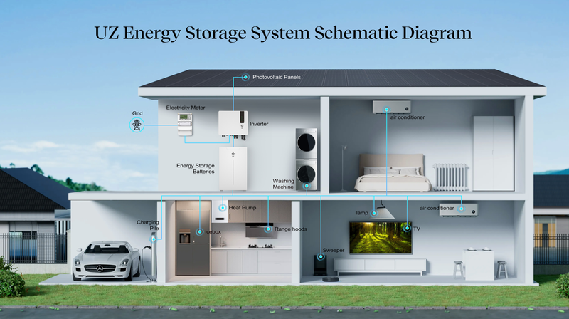
A one-line diagram makes the boundary easier to see. In an AC-coupled solar-plus-storage system, the PV array normally has its own PV inverter and the battery has a separate bidirectional battery inverter or PCS. In a DC-coupled architecture, PV and battery equipment may share a conversion path, but additional DC/DC stages and control logic can sit inside the system.
The practical answer is therefore not that every inverter is simple while every PCS is sophisticated. The inverter is the core conversion stage; PCS is commonly the broader storage power-conversion package. Because industry usage is not perfectly uniform, technical specifications and control responsibilities are the reliable basis for comparison.
Related reading: how the PCS, BMS and EMS work together in a BESS.